
You can now set the individual TDC Enables and the TDC parameters as you desire.
Note these TDC modules are VERY complex modules and options which set parameters for the module microcontroller should be set only when data acquisition is STOPped.
Setting up the CAEN V767/V1190/V1290 TDC
Select MIDAS main menu => VME Module Control => CAEN V767; CAEN V1190; CAEN V1290 or double click on a module in the
VME Configuration and Control Frame
You can now set the individual TDC Enables and the TDC parameters as you desire.
Note these TDC modules are VERY complex modules and options which set parameters for the module microcontroller should be set only when data acquisition is STOPped.
It is VERY strongly advised that before setting up the TDC modules you read the module Technical Information Manual CAREFULLY.
All enabled channels are running continuously. In Trigger Matching mode [this is forced by the software] when a pulse is applied to the trigger input those data items within the current trigger window are written to the data FIFO for the current event. This implies that there can be more than 1 data item for a given channel in an event (multi-hit).
The two most important parameters to consider are the width of the Trigger Window and its Offset with respect to your trigger pulse. This determines if an input signal becomes part of an event. The Trigger OFFSET and Trigger WIDTH are set in units of the module clock period (25ns).
For the V767 WIDTH + OFFSET < 2000 (50us) and for the V1190 WIDTH + OFFSET < 40 (1us). OFFSET can be negative. Hence (particularly for the 1190)
if you are using the TDC to measure the position of an analogue pulse peak the trigger pulse is likely to occur at the end of the analogue signals being measured. WIDTH will be the width of the analogue pulse and OFFSET = -WIDTH.
If you are using Silena 9418 ADCs to measure the analogue pulses then you input into the SAC a trigger signal which is passed to the ADCs and causes them to search for the analogue pulse peak. You should take the MON2 output from the SAC (this is the COM signal from the ADC control bus); delay it by the width of the analogue pulse and apply to the trigger input of the TDCs.
If you are using CAEN ADCs to measure the analogue pulses then you input into the SAC a gate signal. In this case the MON2 output from the SAC is the gate signal passed to the ADCs. You need to convert the MON2 gate signal trailing edge (or the MON2 gate signal leading edge delayed by the width of the analogue pulse) into the trigger signal for the TDCs. Do not attempt to directly use the trailing edge of the ADC gate - it doesn't work!
The trigger signal must have a width of at least 5ns.
For the TDCs set Trigger Window Width (WIDTH) to be the width of the analogue pulse and Window Offset to be -WIDTH. Hence WIDTH + OFFSET = 0 (well within the limit of 40).
Also Enable Subtraction of Trigger Time. All data values are now relative to the start of the trigger window.
These are only basic suggestions about setting up the TDCs. You should also consider the effect of the clock period in both the SAC and TDC (40 MHz - 25ns). For a discussion on this topic and a suggestion for generating the TDC trigger see SAC User Manual
When you have adjusted the TDC parameters as you require click on the button Save Setup. The button Restore Setup will cause all parameters to be restored to this state. Additionally during SETUP of the Data Acquisiton system a Restore Setup will be peformed.
A common mode of use of the TDCs is traditional "Common Stop" mode. This is not directly supported by the hardware but the effect can be achieved. See Common Stop Emulation for a discussion on the way to do this.
For the V1190/V1290 only the item Events Stored is the number of events currently in the module data FIFO. When data acquisition is running the software only allows 1 trigger at a time to be issued by the SAC before starting event readout. Hence mostly you should see Events Stored to be zero. It is possible that you may see the value 1. However if you always see a value greater than 1 then more triggers have been detected by the TDC module than issued by the SAC. This situation is a serious fault and must be investigated.
By default the software creates histograms having the same number of channels as the hardware source.
However since the TDCs potential give 16 bit data this can lead to a large number of large histograms which cannot be supported by the available RAM. 3 options are available which allow control of
the histogram size. For further information see
Experiment Options
The hardware and data acquisition software defines a default setup
V767
| acquisition mode | stop trigger matching |
| channel enable | all channels enabled |
| window width | 100 (2.5us) |
| window offset | 50 (1.25us) |
V1190/V1290
| acquisition mode | trigger matching |
| channel enable | all channels enabled |
| window width | 20 (500ns) |
| window offset | -40 (-1us) |
| extra search margin | 8 (200ns) |
| reject margin | 4 (100ns) |
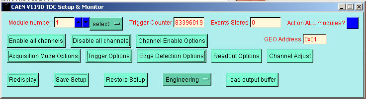
Use the Channel Enable choices to enable or disable all channels or to enable selected channels.
Each of the Options buttons correspond to a class of parameters to the microcontroller and opens a new window.
See some Typical Screen shots of each of these options windows.
By using the Act on ALL checkboxes you can cause a change to act on all modules in your configuration.
GEO Address is the value you used for the Module ID. It cannot be changed here.
The button read output buffer is for diagnostics only